I downloaded a program called DraftSight. I'm trying to input a list of x/y coordinates for a boat building project.
This program doesn't appear to be able to simply input a list of coordinates to produce a drawing. Am I just being dumb, or does anyone know of a simple program to do this?
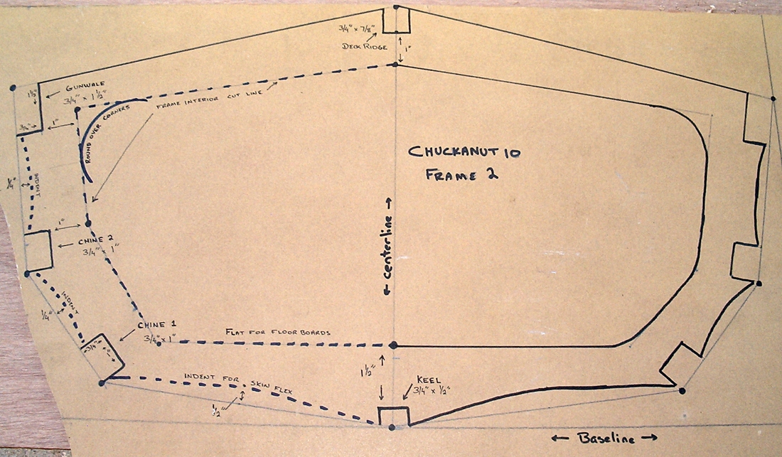
Heres what the coordinates produce when used in real life, something that I can do easily. I just want to do it on the PC to easily print patterns out to build a model. The outer straight lines are all I care about generating.
I guess if I have to I can convert to metric then reduce to 1/10 scale pretty easily. Printing would just save a lot of time if theres a simple way to do this.
Quote:
HB = Half Breadth (1/2 width) HAB = Height Above Baseline
Layout of the frames is just like graphing - over a distance X(HB), then up a distance Y(HAB). Since that will only produce marks for half of a frame, repeat for the other half. Connect marks to create the frame outline.
{0-0/8 is merely a consistent way of saying "zero inches"}
Frame 1 (Fwd)
__________ __________
Keel 0-0/8 0-0/8
Lower Chine 4-2/8 2-3/8
Upper Chine 6-3/8 6-1/8
Gunwale 7-2/8 12-1/8
Deck 0-0/8 12-1/8
This program doesn't appear to be able to simply input a list of coordinates to produce a drawing. Am I just being dumb, or does anyone know of a simple program to do this?
Heres what the coordinates produce when used in real life, something that I can do easily. I just want to do it on the PC to easily print patterns out to build a model. The outer straight lines are all I care about generating.
I guess if I have to I can convert to metric then reduce to 1/10 scale pretty easily. Printing would just save a lot of time if theres a simple way to do this.
o.0